

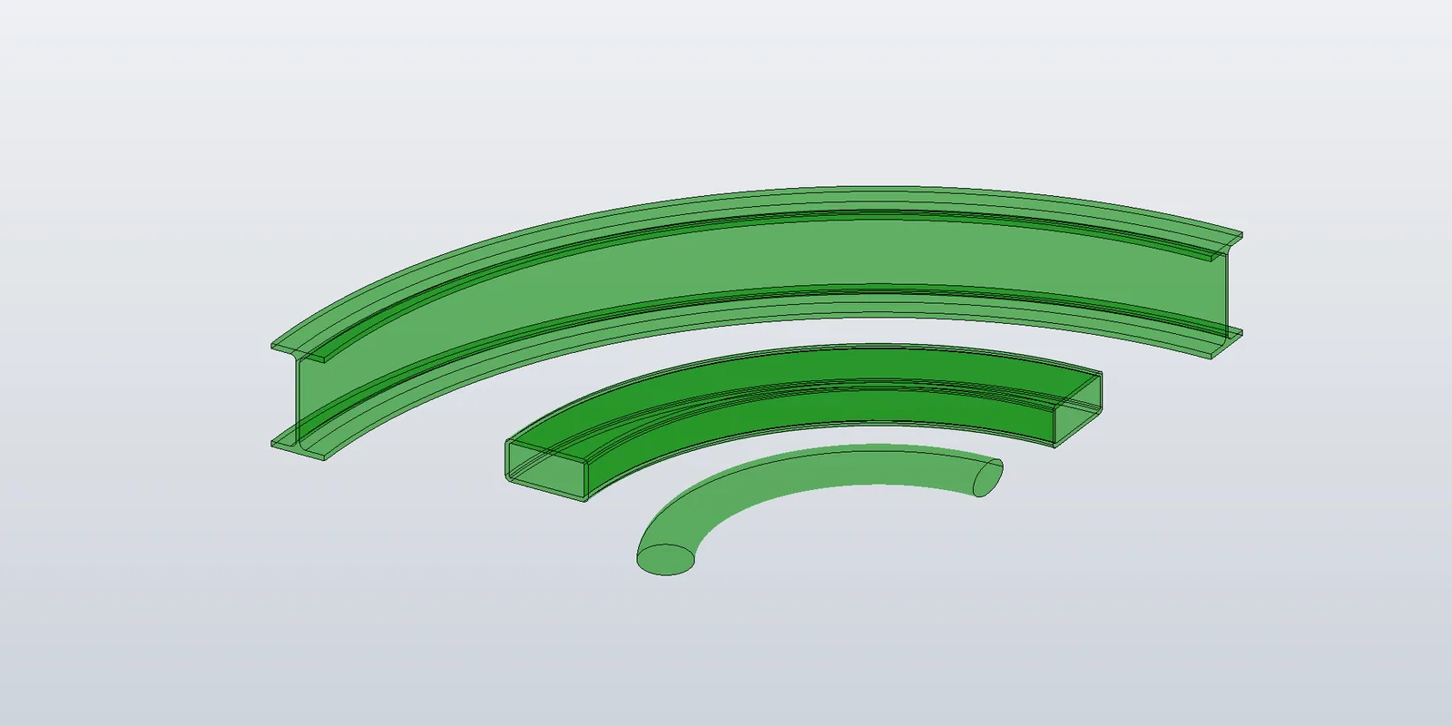
A straight beam's centerline is a Line3D. A profile curve sweeps along it into a plane (line edges) or a cylinder (arc edges), and two surface types cover everything.
A curved beam's centerline is an Arc3D. A line in the profile no longer sweeps to one fixed surface type — it depends on the line's orientation relative to the arc's axis. Profile arcs sweep to tori. Profile ellipses sweep to something that isn't a named TransientGeometry surface at all. The topology is the same as in Post 5; what changes is the connector curve and the surface per profile curve, which is why AddSideFaces there takes both as parameters.
Radial distance and height
A centerline arc has a centre, a normal (its axis) and a radius. Any point has two scalar coordinates relative to that arc: its radial distance from the axis, and its height along the axis measured from the arc's plane.
public static (double RadialDistance, double HeightOffset) GetRadialDistanceAndHeight(Point3D point, Arc3D centerline)
{
    var toPoint = point - centerline.Center;
    var heightOffset = toPoint.Dot(centerline.Normal);
    var radialComponent = toPoint - centerline.Normal * heightOffset;
    return (radialComponent.Length, heightOffset);
}
(BasAutomation.Geometry.Surfaces.SweptSurfaces.LineSweptSurfaceClassifier.) Sweeping a point along the centerline rotates it about the axis by the centerline's sweep angle; its path is a circle of radius radial distance, in the plane at height. Every dispatch below is a comparison of these two numbers at a curve's endpoints.
Placing the profiles and the connectors
The start profile sits on the plane through the arc's start point with normal along the tangent there. The end profile is the start profile rotated about the arc's axis, through the arc's centre, by the sweep angle. Connectors are the circles the profile vertices trace — sweep arcs, concentric with the centerline.
public static SurfaceBody Build(
    Inventor.Application app,
    IReadOnlyList<ICurve3D> outerProfile,
    IReadOnlyList<IReadOnlyList<ICurve3D>> innerProfiles,
    Arc3D centerline)
{
    var geo = new InventorGeometry(app.TransientGeometry);
    var bodyDef  = app.TransientBRep.CreateSurfaceBodyDefinition();
    var shellDef = bodyDef.LumpDefinitions.Add().FaceShellDefinitions.Add();

    var startTangent = centerline.TangentAt(0);
    var endTangent   = centerline.TangentAt(1);
    var atStart  = Profiles.FrameAt(centerline.StartPoint, startTangent);
    var sweep    = Matrix3D.CreateRotationAroundPoint(centerline.Normal, centerline.SweepAngle, centerline.Center);
    var atEnd    = sweep * atStart;

    var startOuter = AddProfileEdges(bodyDef, geo, Profiles.Transform(outerProfile, atStart));
    var endOuter   = AddProfileEdges(bodyDef, geo, Profiles.Transform(outerProfile, atEnd));
    var startInner = innerProfiles.Select(p => AddProfileEdges(bodyDef, geo, Profiles.Transform(p, atStart))).ToList();
    var endInner   = innerProfiles.Select(p => AddProfileEdges(bodyDef, geo, Profiles.Transform(p, atEnd))).ToList();

    AddCapFace(shellDef, geo, new Plane3D(centerline.StartPoint, -startTangent), startOuter, startInner, outwardIsProfileNormal: false);
    AddCapFace(shellDef, geo, new Plane3D(centerline.EndPoint, endTangent), endOuter, endInner, outwardIsProfileNormal: true);

    // Side faces: connectors are sweep arcs; surfaces come from the classifier below.
    object Connector(Point3D p) => geo.Arc(SweepArcThrough(p, centerline));
    object Surface(ICurve3D c)  => SweptSurface(geo, c, centerline);

    Post05_StraightBeam.AddSideFaces(bodyDef, shellDef, Profiles.Transform(outerProfile, atStart), startOuter, endOuter, Connector, Surface);
    for (int k = 0; k < innerProfiles.Count; k++)
        Post05_StraightBeam.AddSideFaces(bodyDef, shellDef, Profiles.Transform(innerProfiles[k], atStart), startInner[k], endInner[k], Connector, Surface);

    var body = bodyDef.CreateTransientSurfaceBody(out NameValueMap errors);
    ThrowIfErrors(errors);
    return body;
}

public static Arc3D SweepArcThrough(Point3D point, Arc3D centerline)
{
    var (radial, height) = LineSweptSurfaceClassifier.GetRadialDistanceAndHeight(point, centerline);
    var sweepCentre = centerline.Center + centerline.Normal * height;
    var toPoint     = (point - sweepCentre).Normalized();
    return new Arc3D(sweepCentre, centerline.Normal, toPoint, radial,
                     startAngle: 0, endAngle: centerline.SweepAngle,
                     isCounterClockwise: centerline.SweepAngle >= 0);
}
Compared with the straight beam's Build, the differences are atEnd (a rotation instead of a translation), the connector (an arc instead of a segment) and the surface function.
Which surface a line sweeps to
Three cases, decided from the endpoints' radial distances and heights:
- Radial — the line points at the axis and both endpoints are at the same height. Sweeping it keeps it in the plane at that height: a plane with normal along the axis.
- Tangential — both endpoints at the same radial distance. The line sweeps around at constant radius: a cylinder coaxial with the centerline, offset along the axis by the line's height.
- Tilted — different radial distances at the two ends: a cone, coaxial with the centerline.
CreateConewants a root point on the axis, the axis direction, the radius at the root, the half-angle, and whether the cone expands along the axis; putting the root at the smaller-radius end with the axis pointing at the larger end makes it always expanding.
public static object SweptSurface(InventorGeometry geo, ICurve3D curve, Arc3D centerline)
{
    var tg = geo.Tg;
    switch (curve)
    {
        case Line3D line:
            switch (LineSweptSurfaceClassifier.Classify(line, centerline))
            {
                case LineSweptSurfaceKind.RadialPlane:
                {
                    var (_, height) = LineSweptSurfaceClassifier.GetRadialDistanceAndHeight(line.MidPoint, centerline);
                    var origin = centerline.Center + centerline.Normal * height;
                    return geo.Pln(new Plane3D(origin, centerline.Normal));
                }
                case LineSweptSurfaceKind.Cylinder:
                {
                    var (center, axis, radius) = CylinderFromArcSweep.Compute(line, centerline);
                    return tg.CreateCylinder(geo.Pt(center), geo.Unit(axis), radius);
                }
                default:
                {
                    var (root, axis, rootRadius, halfAngle) = ConeFromArcSweep.Compute(line, centerline);
                    return tg.CreateCone(geo.Pt(root), geo.Unit(axis), rootRadius, halfAngle, IsExpanding: true);
                }
            }

        case Arc3D arc:
        {
            var (center, axis, major, minor) = TorusFromArcSweep.Compute(arc, centerline);
            return tg.CreateTorus(geo.Pt(center), geo.Unit(axis), major, minor);
        }

        case Circle3D circle:
        {
            var (center, axis, major, minor) = TorusFromArcSweep.Compute(circle, centerline);
            return tg.CreateTorus(geo.Pt(center), geo.Unit(axis), major, minor);
        }

        case Ellipse3D ellipse:
        {
            var (order, poles, knotsU, knotsV, weights, isPeriodic) = BSplineEllipseSweep.ComputeSurface(ellipse, centerline);
            return tg.CreateBSplineSurface(ref order, ref poles, ref knotsU, ref knotsV, ref weights, ref isPeriodic);
        }

        default:
            throw new NotSupportedException(curve.GetType().Name);
    }
}
Classify checks radial first (line direction within ~25° of the radial direction at its midpoint and equal heights), then splits the rest on radial distance: different → cone, equal → cylinder. ConeFromArcSweep.Compute returns the root/axis/radius/half-angle described above; CylinderFromArcSweep and TorusFromArcSweep are the two-line computations from the radial/height decomposition. All of them are in BasAutomation.Geometry.Surfaces.SweptSurfaces.
An RHS oriented with its width along the radial direction has radial top and bottom edges (planes) and tangential side edges (cylinders); rotated 90° about the beam, the same two types swap edges. Only an orientation in between tilts the lines, and that is where the cones show up, as on the I-section rotated 20° below. The dispatch is per curve, so every orientation goes through the same code.
Profile arcs and circles: tori
A profile arc sweeps to a torus. Its axis is the centerline's axis; the major radius is the radial distance of the arc's centre; the minor radius is the arc's radius; the torus centre is on the axis at the arc centre's height. A profile circle is the same torus with two loops on the face, one per cap, and no connectors — exactly the two-loop cylinder from Post 5 with a different surface.
This is where loop orientation stops being optional. The construction-tree post showed that Inventor repairs a flipped loop or normal on the faces of a closed box; the straight-beam builder still walks every loop so the face lies to the left when walking with the surface's own normal up, and noted that tori are the reason. Two measurements make the point.
A CHS with the two-loop walk the other way round (start circle opposed, end circle forward): 4 faces, IsSolid == true, and a volume of 46 387 cm³ against an expected 2 961. 46 387 is the full torus, 2π²·100·5² = 49 348, minus the band. The face was the complement of the band, and the resulting body is still "solid".
An IPE 200 with its four concave root fillets walked forward like the convex arcs: 18 faces, solid, 14 353 cm³ against 2 983. The difference, 11 370, is four full tori of minor radius 1.2 (2π²·100·1.2² = 2 842 each). Each fillet face was the complement of the fillet.
To see what selects the region, one torus band on its own — a single face bounded by two circles 60° apart on a torus of radii 100 / 5, area read back with Face.Evaluator.Area — for every combination of the two loops' isOpposedToEdge and the face's IsParamReversed:
| start loop opposed | end loop opposed | IsParamReversed |
area | |
|---|---|---|---|---|
| false | false | false | 16 449 | complement |
| false | true | false | 3 290 | band |
| true | false | false | 16 449 | complement |
| true | true | false | 3 290 | band |
| false | false | true | 3 290 | band |
| false | true | true | 16 449 | complement |
| true | false | true | 3 290 | band |
| true | true | true | 16 449 | complement |
Expected band area: 2π·5 · 100·(π/3) = 3 290. With IsParamReversed = false, the end loop's direction decides, and IsParamReversed = true inverts the choice. The combination the builder uses — start circle forward, end circle opposed, IsParamReversed = false — is the second row: the loops walked with the face on their left relative to the surface normal. The same rule applied to four-edge loops (opposed = arc.SweepAngle < 0) fixes the fillets. Whatever repair Inventor does on planes and cylinders, it does not do it here, and it does not report anything: the wrong region is a valid face, so the body is a valid solid — just not the one you meant.
Ellipses: an exact B-spline surface
An elliptical profile swept along an arc is not a plane, cylinder, cone, torus or sphere. TransientGeometry.CreateBSplineSurface(order, poles, knotsU, knotsV, weights, isPeriodic) takes any rational B-spline surface, and this one has an exact representation: both an ellipse and a circular arc are exactly rational quadratic B-splines, and their tensor product is the swept surface.
BSplineEllipseSweep.ComputeSurface(ellipse, arc) builds it:
- U (the ellipse): 9 control points — the four axis-end points on the curve and the four corners of the bounding rectangle off the curve, plus the first point again to close — as four quadratic Bézier spans; weights 1 on the curve and 1/√2 at the corners; clamped knots
0 0 0 1 1 2 2 3 3 4 4 4. - V (the arc): the sweep split into n spans of at most 90°; for each ellipse control point, its concentric sweep arc gives 2n+1 control points — the on-arc points with weight 1 and the tangent-intersection points with weight cos(span/2); clamped knots the same way.
- Poles are the tensor product, XYZ interleaved in U-major order; weights are the products; order
[3, 3]; not periodic in either direction.
The face has two loops (start ellipse, end ellipse), like the circle case. Inventor accepts the surface — Face.SurfaceType reads back kBSplineSurface — and the volume comes out exact (table below).
Results
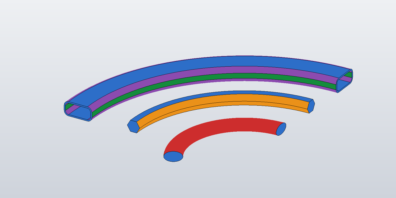
Centerline: radius 100 cm, 60° sweep (arc length 104.72 cm), in the XY plane; the profile plane at the start is perpendicular to the arc, width along the radial direction. Expected volumes are area × arc length (the profiles are symmetric about the centerline, so the centroid is on it).
| profile | faces | surface types | IsSolid |
volume | expected |
|---|---|---|---|---|---|
| 100 × 50 mm rectangle | 6 | 4 plane, 2 cylinder | true | 5235.99 | 5235.99 |
| 100 × 50 mm RHS r 5, 80 × 30 hole | 14 | 6 plane, 4 cylinder, 4 torus | true | 2700.24 | 2700.24 |
| CHS Ø100 / Ø80 | 4 | 2 plane, 2 torus | true | 2960.88 | 2960.88 |
| IPE 200 | 18 | 8 plane, 6 cylinder, 4 torus | true | 2982.85 | 2982.84 |
| ellipse 80 × 40 mm, solid | 3 | 2 plane, 1 B-spline | true | 2631.89 | 2631.89 |
| ellipse 80 × 40 mm, 64 × 24 hole | 4 | 2 plane, 2 B-spline | true | 1368.59 | 1368.59 |
Also checked: the same RHS, CHS and IPE on a clockwise centerline (same volumes); the IPE rotated 20° about the beam so that its lines are neither radial nor tangential and go through the cone case (2982.85); and the IPE on an arc whose axis is (1, 1, 2) and whose start angle isn't zero (2734.47 against 2734.46 for radius 80, sweep 1.2 rad). No case produced an entry in the errors map.
Cutting a curved beam
The extend-then-trim pattern from the angled-ends post applies unchanged in principle — extend the centerline arc by extension / radius radians at each end, build, subtract a cut body per end — with the cut bodies sized as there. That path isn't part of the sample project; the straight-beam trim is.
Where this leaves the series
One skeleton for the whole series. The construction tree from the first posts — SurfaceBodyDefinition, LumpDefinition, FaceShellDefinition, FaceDefinition, EdgeLoopDefinition, EdgeDefinition, VertexDefinition — carries through unchanged; the posts differ in which curves, surfaces and loops fill it. Cap faces and side faces give a straight beam of any profile made of lines, arcs, circles and ellipses; a boolean gives it mitred ends; a GraphicsNode puts it on screen and a key-tracked node manager keeps it there while inputs change; swapping the connector and surface functions gives the curved beam, where the loop-orientation rule that was optional on planes and cylinders becomes the thing that decides which side of a torus you get.
Every code block in the series is lifted from a sample project that compiles against the public BasAutomation.Geometry package and runs against Inventor; the numbers in the tables are what it printed.