

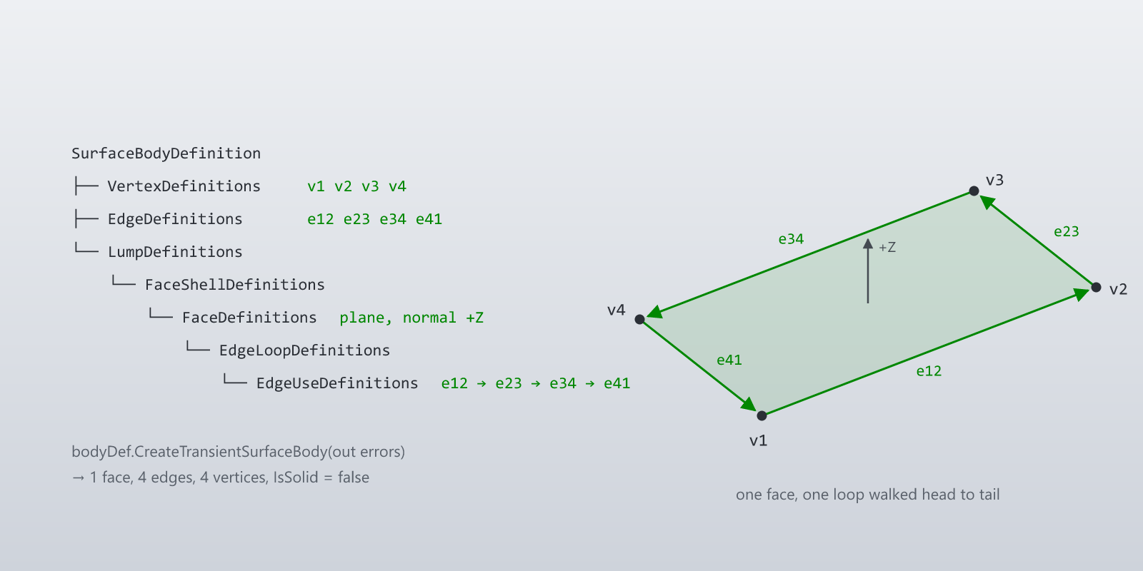
TransientBRep.CreateSurfaceBodyDefinition() returns a SurfaceBodyDefinition. That object is the root of a tree that describes the topology of a SurfaceBody: which vertices exist, which edges connect which vertices, which faces are bounded by which edge loops, and how those faces are grouped into shells and lumps. Once the tree is populated, a single call to CreateTransientSurfaceBody produces the body.
The tree has three levels of nesting:
SurfaceBodyDefinitionowns the topology entities —VertexDefinitionsandEdgeDefinitions— and a list ofLumpDefinitions.LumpDefinitionrepresents one disconnected solid. A body with two completely separate parts has two lumps. Most beams have one. ALumpDefinitionownsFaceShellDefinitions.FaceShellDefinitionis the shell of faces around a lump — the closed boundary in the case of a closed solid, or just the set of faces in the case of an open sheet. It ownsFaceDefinitions.FaceDefinitionis one face: a surface (plane, cylinder, cone, torus, …) plus one or more edge loops that bound the surface to make a face.
Edges aren't owned by faces — they're owned at the body level. Each face references body-level edges via EdgeLoopDefinitions and EdgeUseDefinitions. The reason for the separation is that two adjacent faces share an edge: the edge appears in both faces' loops, once in each direction.
SurfaceBodyDefinition
├── VertexDefinitions    (corner points)
├── EdgeDefinitions      (edges between vertices, each carrying a curve)
└── LumpDefinitions
    └── FaceShellDefinitions
        └── FaceDefinitions
            └── EdgeLoopDefinitions
                └── EdgeUseDefinitions  (reference EdgeDefinitions, with an opposed flag)
TransientGeometry provides the surfaces and curves that go into the definitions. The ones the series uses:
CreatePlane(rootPoint, normal)for planar faces. The normal is aVector, not aUnitVector.CreateCylinder(rootPoint, axis, radius)for cylindrical faces (axisis aUnitVector).CreateCone(rootPoint, axis, radius, halfAngle, isExpanding)for conical faces.CreateTorus(centerPoint, axis, majorRadius, minorRadius)for toroidal faces.CreateBSplineSurface(order, poles, knotsU, knotsV, weights, isPeriodic)for everything else.CreateLineSegment(p1, p2)for line edges.CreateArc3d(center, normal, referenceVector, radius, startAngle, sweepAngle)andCreateCircle(center, normal, radius)for arc and circle edges.CreateEllipseFull(center, normal, majorAxisVector, minorMajorRatio)for full ellipses.
The geometry package and the interop bridge
Every code sample in this series compiles. That takes two libraries: Inventor's COM API, and a small managed geometry library for the maths that Inventor's Point / Vector / Arc3d types don't do conveniently — vector arithmetic, arc endpoints, rigid transforms, and (in the curved-beam post) the radial/height decomposition of a point about an axis.
That managed library is BasAutomation.Geometry: a dependency-free set of value types — Point3D, Vector3D, Matrix3D, Plane3D in BasAutomation.Geometry, and Line3D, Arc3D, Circle3D, Ellipse3D (all ICurve3D) in BasAutomation.Geometry.Curves — with the operators and helpers you'd expect ((end - start).Normalized(), arc.SweepAngle, arc.IsCounterClockwise, matrix.Transform(point)). It has no Inventor dependency, so it stays usable in unit tests and non-CAD code.
dotnet add package BasAutomation.Geometry
The two type systems don't meet on their own: TransientGeometry.CreateCylinder wants an Inventor Point and UnitVector, not a managed Point3D / Vector3D. The join is a thin bridge — one converter per type — constructed against a TransientGeometry:
using Inventor;
using BasAutomation.Geometry;
using BasAutomation.Geometry.Curves;

// A thin adapter from managed geometry to Inventor's COM geometry.
public sealed class InventorGeometry(TransientGeometry tg)
{
    public TransientGeometry Tg => tg;

    public Point          Pt(Point3D p)    => tg.CreatePoint(p.X, p.Y, p.Z);
    public UnitVector     Unit(Vector3D v) => tg.CreateUnitVector(v.X, v.Y, v.Z);
    public Vector         Vec(Vector3D v)  => tg.CreateVector(v.X, v.Y, v.Z);
    public Inventor.Plane Pln(Plane3D pl)  => tg.CreatePlane(Pt(pl.Origin), Vec(pl.Normal));
    public LineSegment    Seg(Line3D l)    => tg.CreateLineSegment(Pt(l.StartPoint), Pt(l.EndPoint));
}
That's the whole pattern: model the geometry in managed types, convert at the boundary. The bridge grows by one method each time a new curve type appears — Arc3d, Circle and EllipseFull in the next post. Surfaces are created inline from bridged arguments. Everything else in the series is Inventor's own topology API, which needs no adapter.
The smallest valid body
A rectangular planar sheet — one face, four vertices, four edges, one loop — exercises every type in the tree. The corner points and edge curves are modelled as managed geometry; the geo bridge converts them as they go into the definition tree.
var transientBRep = app.TransientBRep;
var geo = new InventorGeometry(app.TransientGeometry);

// Four corner points (centimetres — Inventor's internal unit).
var p1 = new Point3D(0, 0, 0);
var p2 = new Point3D(10, 0, 0);
var p3 = new Point3D(10, 5, 0);
var p4 = new Point3D(0, 5, 0);

// The four sides as line segments, and the plane the face sits on.
var l12 = new Line3D(p1, p2);
var l23 = new Line3D(p2, p3);
var l34 = new Line3D(p3, p4);
var l41 = new Line3D(p4, p1);
var plane = new Plane3D(p1, Vector3D.ZAxis);

// Build the topology tree.
var bodyDef  = transientBRep.CreateSurfaceBodyDefinition();
var lumpDef  = bodyDef.LumpDefinitions.Add();
var shellDef = lumpDef.FaceShellDefinitions.Add();

// Vertex definitions go on the body.
var v1 = bodyDef.VertexDefinitions.Add(geo.Pt(p1));
var v2 = bodyDef.VertexDefinitions.Add(geo.Pt(p2));
var v3 = bodyDef.VertexDefinitions.Add(geo.Pt(p3));
var v4 = bodyDef.VertexDefinitions.Add(geo.Pt(p4));

// Edge definitions reference vertex definitions and carry a curve.
var e12 = bodyDef.EdgeDefinitions.Add(v1, v2, geo.Seg(l12));
var e23 = bodyDef.EdgeDefinitions.Add(v2, v3, geo.Seg(l23));
var e34 = bodyDef.EdgeDefinitions.Add(v3, v4, geo.Seg(l34));
var e41 = bodyDef.EdgeDefinitions.Add(v4, v1, geo.Seg(l41));

// One face on the plane, with one edge loop that walks the four edges.
var faceDef = shellDef.FaceDefinitions.Add(geo.Pln(plane), false);
var loop    = faceDef.EdgeLoopDefinitions.Add();
loop.EdgeUseDefinitions.Add(e12, false);
loop.EdgeUseDefinitions.Add(e23, false);
loop.EdgeUseDefinitions.Add(e34, false);
loop.EdgeUseDefinitions.Add(e41, false);

// Build. Errors come back through an out parameter.
var sheet = bodyDef.CreateTransientSurfaceBody(out NameValueMap errors);
The result is a SurfaceBody with 1 face, 4 edges, 4 vertices and IsSolid == false.
Three details in this code matter beyond the tree shape itself.
Edges go from start vertex to end vertex along a curve. EdgeDefinitions.Add(v1, v2, curve) declares an edge from v1 to v2 along curve. The curve is passed as object (the parameter is typed Object ModelSpaceCurve) — any TransientGeometry curve goes in.
Edge loops walk head to tail. Each EdgeUseDefinitions.Add(edge, isOpposedToEdge) call appends an edge to the loop. The end vertex of the previous edge use has to equal the start vertex of the current one. isOpposedToEdge lets a loop walk an edge backwards without redefining it; that is how two adjacent faces share one edge in opposite directions.
The second argument to FaceDefinitions.Add is IsParamReversed. FaceDefinitions.Add(surfaceGeometry, isParamReversed) — the boolean states that the face's normal is opposite to the surface's parametric normal. What it actually does at build time is covered below.
What Inventor does with orientation
The definition tree carries three orientation signals — the loop's winding, the plane's normal, and IsParamReversed. Building the sheet above in every combination and reading back the face normal with Face.Evaluator.GetNormalAtPoint gives:
| loop (viewed from +Z) | IsParamReversed |
resulting face normal |
|---|---|---|
| counter-clockwise | false | +Z |
| counter-clockwise | true | +Z |
| clockwise | false | −Z |
| clockwise | true | −Z |
On an open sheet the loop winding decides the face normal; IsParamReversed doesn't change the result. On a closed solid (the beams later in the series) it goes further: a flipped loop, a flipped plane normal, or IsParamReversed = true on one face of a box all still produce a valid solid with every face normal pointing outward. Inventor reorients faces to make the shell consistent. The one surface where orientation is not repaired is the torus, where both sides of a loop are finite regions — that shows up with the curved beam later in the series.
Reading errors
CreateTransientSurfaceBody(out NameValueMap errors) returns the body and fills the map. When nothing went wrong the map comes back null, not empty, so guard for both:
if (errors != null && errors.Count > 0)
{
    var messages = new List<string>();
    for (int i = 1; i <= errors.Count; i++)
        messages.Add($"{errors.Name[i]}: {errors.Value[errors.Name[i]]}");
    throw new InvalidOperationException(
        $"Surface body creation errors: {string.Join("; ", messages)}");
}
Each reported problem is three entries, Message N Severity, Message N Error Code and Message N Entity AssociativeID. Leaving one edge out of a face's loop on a six-face box, for instance, gives:
Message 1 Severity = Warning
Message 1 Error Code = Error in loop data
Message 1 Entity AssociativeID = EdgeLoopDefinition
and still returns a body — one with 6 faces but 15 edges instead of 12, and IsSolid == false. Two other mistakes produce no entry at all: leaving a face out of a closed shell (5 faces, not solid), and a face whose plane does not contain its loop (extra edges, not solid). errors being null therefore does not mean the body is what you meant. For a closed body, check SurfaceBody.IsSolid as well; for a sheet, check the face and edge counts.
Curves versus vertices
EdgeDefinitions.Add(v1, v2, curve) takes both the vertices and a curve with its own endpoints, so the two can disagree. When they do, the vertex positions win: a line segment ending 1 cm past its vertex still produces an edge from v1 to v2, the face area is unchanged, and nothing is reported. The curve supplies the shape, the vertices supply the extent. That is convenient — the same infinite-plane and full-circle surfaces work as trimmed edges — but it also means a wrong endpoint won't be caught for you. Constructing each Point3D once and reusing it for both the vertex and the curves that meet there, as the sample does with p1…p4, keeps them agreeing by construction.
The plate above is short on purpose. Everything in the rest of the series adds faces, edges, and surfaces to this same skeleton — the cap-and-side beam in the next posts is more of the same topology with more entries; the curved beam later in the series is the same skeleton with cylindrical, conical, toroidal and B-spline surfaces in place of planes; the rendering and updating posts take the resulting SurfaceBody to the viewport.
The code in this post — the adapter and BuildSheet — is in the sample repository at github.com/Basnederveen/TransientGraphicsSamples (InventorGeometry.cs, Post02_ConstructionTree.cs); it builds against the NuGet package and the Inventor interop assembly.
Next post: getting this sheet on screen — the class that owns the client graphics, and a console application that draws it into the running Inventor.