

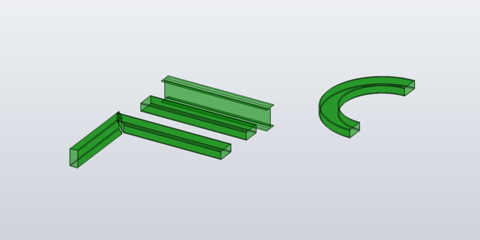
A transient body in Inventor is a SurfaceBody that lives outside the document. It has no undo entry, no part feature, no sketch underneath it. You build it from code, hold it in a variable, render it into the viewport as a preview, or convert it to a permanent feature later. Inventor's API exposes the building blocks, and the names are clear once you know them: SurfaceBodyDefinition, LumpDefinition, FaceShellDefinition, FaceDefinition, EdgeLoopDefinition, EdgeDefinition, VertexDefinition. Surfaces and curves come from TransientGeometry. Together they're enough to construct any geometry the modelling kernel can represent.
What's missing is documentation. Most public Inventor add-in tutorials cover the in-document path — sketch, then extrude or revolve or sweep, then commit — and stop there. The transient construction path, where you build the topology directly without going through a sketch or a feature, is barely documented outside Autodesk's own SDK samples, and the SDK samples mostly demonstrate primitive shapes rather than realistic geometry.
For simple shapes, Inventor exposes a handful of one-shot constructors:
var cylinder = transientBRep.CreateSolidCylinderCone(bottom, top, r1, r1, r1);
var sphere   = transientBRep.CreateSolidSphere(centre, radius);
var box      = transientBRep.CreateSolidBlock(box);
Those cover a few shapes. For everything else — every profile that isn't a circle, every shape with a hole through it, every body that's swept along a path — the construction path is SurfaceBodyDefinition, vertex by vertex and face by face.
This series walks that path end to end, with a beam as the running example. A beam works well as a vehicle for a few reasons:
- The simplest version (straight, perpendicular ends, rectangular profile) introduces planar cap faces and planar side faces — the minimum viable shape to write down.
- A profile with arcs in it (a rounded RHS, an I-section with root fillets, a CHS) forces cylindrical side faces and shows where the head-to-tail edge loop convention starts to bite.
- Hollow sections introduce face definitions with multiple edge loops.
- Angled cut planes at the ends are handled with an "extend then trim" pattern rather than a second builder.
- A curved centerline pushes the same API into conical, toroidal and — for elliptical profiles — B-spline side surfaces, and turns up the one place where Inventor does not repair a loop that's walked the wrong way.
The rest of the series covers, in order: the construction tree itself and what Inventor does with the errors map, loop winding and mismatched curves; getting a body on screen — the class that owns the client graphics, and a console application that draws into the running Inventor; cap faces — profile-shaped planar faces, including hollow sections; side faces connecting two profiles, with the line/arc/closed-curve dispatch; clean angled ends via extend-then-trim; rendering the resulting body as client graphics; updating the rendering in real time when inputs change; and curved beams, where each profile-curve type produces a different swept surface.
Code in the posts calls Inventor directly: Inventor.Application, TransientBRep, TransientGeometry, TransientObjects, ClientGraphics, GraphicsNode. For the vector arithmetic and rigid transforms that Inventor's own Point / Vector types don't do conveniently, the samples use a small managed geometry library, BasAutomation.Geometry (MIT, source on GitHub, published as a NuGet package), and a ~40-line bridge that converts its types to Inventor's — set up once in the next post. Every code block is lifted from a sample project that compiles against that package and the Inventor interop assembly and runs against a live Inventor; the face counts, volumes and areas quoted in the posts are what it printed. That sample project is public at github.com/Basnederveen/TransientGraphicsSamples; each post's code is added to it when the post goes out, so it can be cloned and run rather than reassembled from the posts.
Next post: the SurfaceBodyDefinition tree itself, walked through with the smallest valid body — a single rectangular planar sheet.