

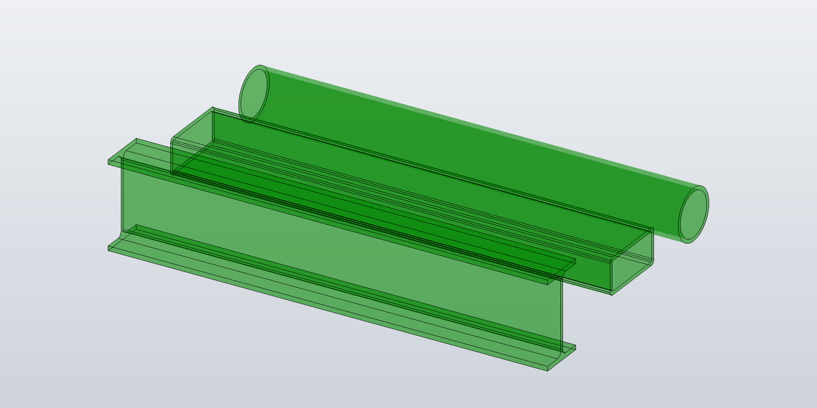
The cap faces from the previous post are two disconnected planar shapes. To build a closed beam, the caps are connected by side faces — one face per profile curve. For an RHS with four line edges that's four side faces; for a rounded RHS eight; for an I-section with root fillets sixteen.
Each side face is bounded by a four-edge loop:
  start_curve_start ─────start curve───── start_curve_end
        │                                       │
   connector[i]                           connector[i+1]
        │                                       │
  end_curve_start  ───end curve (opposed)── end_curve_end
Read head to tail: the start curve, then the connector from the start curve's end-point along the beam to the corresponding point on the end profile, then the end curve walked in the opposite direction, then the connector back to the start. Adjacent side faces share their connector, and every side face shares its start and end curve with the caps — the ProfileTopology from Post 4 holds exactly those edges.
The surface of the face depends on the profile curve type. A line sweeps to a plane. An arc sweeps to a cylinder — the arc's normal is the cylinder's axis, the arc's radius its radius. A closed curve sweeps to a cylinder (or elliptical cylinder) with two separate edge loops, one per cap, and no connectors.
Placing the profile
Profiles are drawn in XY around the origin. FrameAt gives the rigid transform that puts that plane at a point with its +Z along the beam direction; Transform applies a Matrix3D to every curve type in a profile.
// Frame that maps the XY profile plane onto a plane through `origin` with normal `direction`.
public static Matrix3D FrameAt(Point3D origin, Vector3D direction) =>
    Matrix3D.CreateRotationFromTo(Vector3D.ZAxis, direction.Normalized()).SetTranslation(origin);

public static IReadOnlyList<ICurve3D> Transform(IReadOnlyList<ICurve3D> profile, Matrix3D m) =>
    profile.Select(c => Transform(c, m)).ToList();

public static ICurve3D Transform(ICurve3D curve, Matrix3D m) => curve switch
{
    Line3D l    => new Line3D(m.Transform(l.StartPoint), m.Transform(l.EndPoint)),
    Arc3D a     => new Arc3D(m.Transform(a.Center), m.Transform(a.Normal), m.Transform(a.XAxis),
                             a.Radius, a.StartAngle, a.EndAngle, a.IsCounterClockwise),
    Circle3D k  => new Circle3D(m.Transform(k.Center), k.Radius, m.Transform(k.Normal)),
    Ellipse3D e => new Ellipse3D(m.Transform(e.Center), e.SemiMajorAxis, e.SemiMinorAxis,
                                 m.Transform(e.Normal), m.Transform(e.MajorAxisDirection)),
    _ => throw new NotSupportedException(curve.GetType().Name),
};
The straight-beam builder
Caps at both ends with the previous post's code, then side faces for the outer loop and each inner loop:
public static SurfaceBody Build(
    Inventor.Application app,
    IReadOnlyList<ICurve3D> outerProfile,
    IReadOnlyList<IReadOnlyList<ICurve3D>> innerProfiles,
    Point3D start, Vector3D direction, double length)
{
    var geo = new InventorGeometry(app.TransientGeometry);
    var bodyDef  = app.TransientBRep.CreateSurfaceBodyDefinition();
    var shellDef = bodyDef.LumpDefinitions.Add().FaceShellDefinitions.Add();

    direction = direction.Normalized();
    var end = start + direction * length;
    var atStart = Profiles.FrameAt(start, direction);
    var atEnd   = Profiles.FrameAt(end, direction);

    // Cap topology for every loop, at both ends.
    var startOuter = AddProfileEdges(bodyDef, geo, Profiles.Transform(outerProfile, atStart));
    var endOuter   = AddProfileEdges(bodyDef, geo, Profiles.Transform(outerProfile, atEnd));
    var startInner = innerProfiles.Select(p => AddProfileEdges(bodyDef, geo, Profiles.Transform(p, atStart))).ToList();
    var endInner   = innerProfiles.Select(p => AddProfileEdges(bodyDef, geo, Profiles.Transform(p, atEnd))).ToList();

    AddCapFace(shellDef, geo, new Plane3D(start, -direction), startOuter, startInner, outwardIsProfileNormal: false);
    AddCapFace(shellDef, geo, new Plane3D(end, direction), endOuter, endInner, outwardIsProfileNormal: true);

    // Side faces: connectors are straight segments along the beam; surfaces are planes and cylinders.
    object Connector(Point3D p) => geo.Seg(new Line3D(p, p + direction * length));
    object Surface(ICurve3D c)  => SideSurface(geo, c, direction);

    AddSideFaces(bodyDef, shellDef, Profiles.Transform(outerProfile, atStart), startOuter, endOuter, Connector, Surface);
    for (int k = 0; k < innerProfiles.Count; k++)
        AddSideFaces(bodyDef, shellDef, Profiles.Transform(innerProfiles[k], atStart), startInner[k], endInner[k], Connector, Surface);

    var body = bodyDef.CreateTransientSurfaceBody(out NameValueMap errors);
    ThrowIfErrors(errors);
    return body;
}
AddSideFaces is parameterised on two functions — the connector curve a profile vertex traces from start cap to end cap, and the surface a profile curve sweeps to — because those are the only two things that differ between a straight beam and a curved one.
Side faces
public static void AddSideFaces(
    SurfaceBodyDefinition bodyDef, FaceShellDefinition shellDef,
    IReadOnlyList<ICurve3D> startProfile, ProfileTopology startTopo, ProfileTopology endTopo,
    Func<Point3D, object> connector, Func<ICurve3D, object> surface)
{
    int n = startProfile.Count;

    // One connector edge per profile vertex.
    var connectors = new EdgeDefinition[n];
    for (int j = 0; j < n; j++)
        connectors[j] = bodyDef.EdgeDefinitions.Add(startTopo.Vertices[j], endTopo.Vertices[j], connector(startProfile[j].StartPoint));

    for (int i = 0; i < n; i++)
    {
        var curve   = startProfile[i];
        var faceDef = shellDef.FaceDefinitions.Add(surface(curve), false);

        // Loops are walked so the face lies to the LEFT when walking with the surface's own
        // normal up. For a profile curve that is: forward along the curve if it runs
        // counter-clockwise about the beam direction (a convex arc, a circle), opposed if it
        // runs clockwise (a concave fillet). Planes and cylinders forgive the wrong choice;
        // tori (curved beams, later in the series) do not.
        bool opposed = curve is Arc3D a && a.SweepAngle < 0;

        if (Profiles.IsClosedCurve(curve))
        {
            // Two loops, one per cap, no connectors: start circle forward, end circle opposed.
            var startLoop = faceDef.EdgeLoopDefinitions.Add();
            startLoop.EdgeUseDefinitions.Add(startTopo.Edges[i], false);
            var endLoop = faceDef.EdgeLoopDefinitions.Add();
            endLoop.EdgeUseDefinitions.Add(endTopo.Edges[i], true);
            continue;
        }

        // Four-edge loop: start curve, connector to the end cap, end curve back, connector home.
        int next = (i + 1) % n;
        var loop = faceDef.EdgeLoopDefinitions.Add();
        if (!opposed)
        {
            loop.EdgeUseDefinitions.Add(startTopo.Edges[i], false);
            loop.EdgeUseDefinitions.Add(connectors[next],   false);
            loop.EdgeUseDefinitions.Add(endTopo.Edges[i],   true);
            loop.EdgeUseDefinitions.Add(connectors[i],      true);
        }
        else
        {
            loop.EdgeUseDefinitions.Add(startTopo.Edges[i], true);
            loop.EdgeUseDefinitions.Add(connectors[i],      false);
            loop.EdgeUseDefinitions.Add(endTopo.Edges[i],   false);
            loop.EdgeUseDefinitions.Add(connectors[next],   true);
        }
    }
}
The opposed rule is the one non-obvious line. A face on a surface is the region on one side of its loops; Inventor takes the region to the left of the loop when walking it with the surface's own normal pointing up. For a convex arc walked counter-clockwise about the beam direction, that puts the face on the sweep side of the start curve, as it should be. For a concave arc (an I-section root fillet), which the counter-clockwise profile walks clockwise, the same forward walk puts the face on the wrong side, and the loop has to be walked the other way round. On planes and cylinders the "wrong side" is an infinite region and Inventor picks the finite one regardless — the straight I-section builds correctly with either walk. On a torus both sides are finite, and the wrong walk yields the complement of the face; Post 9 shows the numbers.
Surfaces for a straight beam
public static object SideSurface(InventorGeometry geo, ICurve3D curve, Vector3D direction)
{
    switch (curve)
    {
        case Line3D l:
            // Plane through the line; normal = (line direction × beam direction), which for a
            // counter-clockwise profile is the outward normal.
            return geo.Pln(new Plane3D(l.StartPoint, l.Direction.Cross(direction).Normalized()));
        case Arc3D a:
            // Cylinder coaxial with the arc.
            return geo.Tg.CreateCylinder(geo.Pt(a.Center), geo.Unit(a.Normal), a.Radius);
        case Circle3D c:
            return geo.Tg.CreateCylinder(geo.Pt(c.Center), geo.Unit(c.Normal), c.Radius);
        case Ellipse3D e:
            return geo.Tg.CreateEllipticalCylinder(geo.Pt(e.Center), geo.Unit(e.Normal),
                geo.Vec(e.MajorAxisDirection * e.SemiMajorAxis), e.SemiMinorAxis / e.SemiMajorAxis);
        default:
            throw new NotSupportedException(curve.GetType().Name);
    }
}
The profile plane is perpendicular to the beam, so a profile arc's normal is parallel to the beam direction — the cylinder's axis is the beam direction and its root point the arc's centre. That single construction covers every arc on a straight beam.
Results
Built and measured on Inventor 2026 with SurfaceBody.Volume; all beams 100 cm long:
| profile | faces | edges | IsSolid |
volume (cm³) | expected |
|---|---|---|---|---|---|
| 100 × 50 mm rectangle, 100 cm long | 6 | 12 | true | 5000.00 | 5000.00 |
| 100 × 50 mm RHS, r 5, 80 × 30 hole | 14 | 36 | true | 2578.54 | 2578.54 |
| CHS Ø100 / Ø80 | 4 | 4 | true | 2827.43 | 2827.43 |
| IPE 200 (with root fillets) | 18 | 48 | true | 2848.41 | 2848.40 |
The rectangle also comes out at 5000.00 when built from (1, 2, 3) along (1, 1, 0) — the frame transform is doing its job. The RHS's 36 edges are 8 per cap outer, 4 per cap inner, 8 outer connectors and 4 inner connectors, all shared: no duplicate topology anywhere in the body.
Independent faces are stitched too
The builder above shares vertices and edges between faces because it has them to hand. Inventor does not require it. A six-face box built with every face defining its own four vertices and four edges — 24 vertex definitions and 24 edge definitions at coincident positions — comes out as the same 8-vertex, 12-edge solid with the same volume. CreateTransientSurfaceBody merges coincident vertices and coincident edges. Sharing keeps the definition tree smaller and makes the connector between two side faces one edge by construction, but it isn't what makes the shell close.
The next post covers beams whose ends aren't perpendicular to the centerline: build over-long with the code above, then trim.