

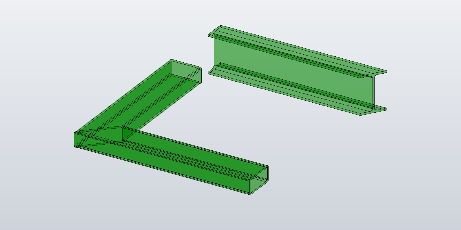
The beam from the previous posts has perpendicular ends — the cap planes sit at right angles to the centerline. Beams that meet other beams have mitred ends: the cap is a plane at some angle to the centerline, the side faces have unequal lengths, and for a profile with arcs the cap edges become elliptical arcs.
The straight-beam builder from the previous post doesn't handle any of that. Instead, the beam is built over-long with perpendicular ends, and each end is trimmed with a transient cut body whose flat face lies on the cut plane. The perpendicular builder stays as it is; TransientBRep.DoBoolean produces the angled cap and trims the side faces.
The trim
Inputs: the outer and inner profiles, the centerline from start to end, and a cut plane at each end. The plane normals can point either way; which side holds the beam is worked out from the centerline.
public static SurfaceBody Build(
    Inventor.Application app,
    IReadOnlyList<ICurve3D> outerProfile,
    IReadOnlyList<IReadOnlyList<ICurve3D>> innerProfiles,
    Point3D start, Point3D end,
    Plane3D startCut, Plane3D endCut)
{
    var direction = (end - start).Normalized();
    var length    = start.DistanceTo(end);

    // 1. How far past each cut plane the beam has to be built.
    var diagonal       = ProfileDiagonal(outerProfile);
    var startExtension = ExtensionForCut(AngleFromPerpendicular(startCut, direction), diagonal);
    var endExtension   = ExtensionForCut(AngleFromPerpendicular(endCut,   direction), diagonal);

    // 2. Elongate the centerline by those amounts.
    var elongatedStart  = start - direction * startExtension;
    var elongatedLength = length + startExtension + endExtension;

    // 3. Build the over-long beam with perpendicular ends (the previous posts).
    var beam = Post05_StraightBeam.Build(app, outerProfile, innerProfiles, elongatedStart, direction, elongatedLength);

    // 4. Subtract a cut body at each end. DoBoolean mutates its first argument.
    var startTool = CutBody(app, startCut, awayFromBeam: -direction, reach: startExtension + diagonal);
    var endTool   = CutBody(app, endCut,   awayFromBeam:  direction, reach: endExtension + diagonal);
    app.TransientBRep.DoBoolean(beam, startTool, BooleanTypeEnum.kBooleanTypeDifference);
    app.TransientBRep.DoBoolean(beam, endTool,   BooleanTypeEnum.kBooleanTypeDifference);
    return beam;
}
DoBoolean(blankBody, toolBody, booleanType) modifies blankBody in place; there is no return value. kBooleanTypeDifference removes the tool's volume from the blank.
How far to extend
Take a cut plane whose normal makes an angle θ with the centerline (θ = 0 is a square cut). The plane crosses the beam's cross-section over an axial span of d · tan θ, where d is the diagonal of the profile's bounding box, so the beam has to reach at least (d / 2) · tan θ past the point where the centerline meets the plane — otherwise the perpendicular cap is still partly there after the cut. The extension used is more generous than that minimum:
// Angle between the cut plane's normal and the centerline, folded into [0, π/2].
public static double AngleFromPerpendicular(Plane3D cutPlane, Vector3D direction)
{
    var cos = Math.Abs(cutPlane.Normal.Normalized().Dot(direction.Normalized()));
    return Math.Acos(Math.Min(1.0, cos));
}

// 1.5 · diagonal / cos θ, plus a 1 cm margin.
public static double ExtensionForCut(double angleFromPerpendicular, double diagonal)
{
    if (angleFromPerpendicular < 1e-6) return 0;

    var cos = Math.Cos(angleFromPerpendicular);
    if (cos < 1e-3)
        throw new ArgumentException("Cut plane is too close to parallel with the centerline.");

    return 1.5 * diagonal / cos + 1.0;
}

public static double ProfileDiagonal(IReadOnlyList<ICurve3D> profile)
{
    // Sample each curve; good enough for a bounding box.
    var pts = profile.SelectMany(c => Enumerable.Range(0, 17).Select(i => c.PointAt(i / 16.0))).ToList();
    double w = pts.Max(p => p.X) - pts.Min(p => p.X);
    double h = pts.Max(p => p.Y) - pts.Min(p => p.Y);
    return Math.Sqrt(w * w + h * h);
}
The 1.5 factor covers profiles whose centerline isn't at the centroid (channels, angles, offset insert points), where the centerline-to-corner distance can exceed half the diagonal. The + 1.0 is a centimetre of margin so that a cut a few degrees off square, where cos θ ≈ 1 and the extension is short, doesn't rely on the boolean resolving a near-coincident face. The cos < 1e-3 guard (89.94°) rejects cuts that are nearly parallel to the beam, where the extension would be more than 1500 times the profile diagonal.
How big the cut body has to be
The cut body is a square block sitting on the cut plane and extruded away from the beam. It has to swallow the whole over-long stub. Every point of the stub lies within extension + d of the point where the centerline meets the plane — the stub is extension long and the profile is within d of the centerline — so a block 2 · (extension + d) on a side and extension + d deep covers it with room to spare. The block is deliberately oversized; nothing depends on it being tight.
private static SurfaceBody CutBody(Inventor.Application app, Plane3D cutPlane, Vector3D awayFromBeam, double reach)
{
    var n = cutPlane.Normal.Normalized();
    if (n.Dot(awayFromBeam) < 0) n = -n;
    return Post05_StraightBeam.Build(app, Profiles.Rectangle(2 * reach, 2 * reach), [], cutPlane.Origin, n, reach);
}
The block comes from the same straight-beam builder — a rectangle profile, extruded along the plane normal. Six planar faces, twelve edges, eight vertices.
Results
Built and measured on Inventor 2026 with SurfaceBody.Volume: a 100 × 50 mm rectangle, centerline from (0, 0, 0) to (0, 0, 100) (cm), start cut plane through the origin rotated about Y by θ, end cut square. A plane through the centerline endpoint removes as much as it adds, so the volume should stay 5000 cm³:
| θ | faces | IsSolid |
volume (cm³) |
|---|---|---|---|
| 0° | 6 | true | 5000.00 |
| 30° | 6 | true | 5000.00 |
| 45° | 6 | true | 5000.00 |
| 60° | 6 | true | 5000.00 |
| 80° | 6 | true | 5000.00 |
The same holds with both ends cut at 45°, and for the other sections from the previous post with both ends at 30°: the rounded RHS with its inner contour (14 faces, 2578.54 cm³) and the CHS (4 faces, 2827.43 cm³).
At 89° the same beam gives 5 faces and 6517 cm³. The trim itself works as intended: a plane at 89° through the start point crosses a 10 cm wide section over 10 · tan 89° ≈ 573 cm of length, so it also crosses the far end of a 100 cm beam. A cut plane that reaches the other end of the beam is an input error; check for it before calling the builder.
Why not build directly between the angled planes
The straight builder can't: it places the same profile at both ends and connects corresponding vertices with straight connectors, which assumes both caps are perpendicular to the beam. Sampling the profile on angled planes instead means a different curve type per cap (arcs become elliptical arcs), side surfaces trimmed by planes rather than bounded by profile curves, and connectors of unequal length. All of that is expressible in the topology API, but it is a different builder. Extend-then-trim leaves the perpendicular builder untouched and lets the boolean do the trimming.
The next post covers how the body is drawn: colour and opacity, edges, and node transforms.