
In heavy fabrication and shipbuilding, bent plates are often inherited from legacy CAD as solid parts where the bend radius has been approximated by a chain of short fillet segments. These parts cannot be unfolded by Inventor's sheet metal engine — so they cannot go straight to the laser cutter or press brake. The Bent Plate Converter rewrites the geometry into a clean, parametric sheet metal part automatically, so production-ready flat patterns become a single button click.
The add-in installs a "Bas Automation" tab in both the Part and Assembly ribbon environments, with a Plate Radius panel offering three actions: convert the active part, convert a single picked occurrence inside an assembly, or sweep the whole assembly and convert every plate it contains. The assembly-level command shows live progress in Inventor's status bar so the user can see exactly how far the batch has gotten.

The Plate Radius panel as it appears in the Part environment — one command, no dialog, no options to get wrong.
For each plate, the add-in inspects the solid body to identify the two largest parallel faces (the plate sides), the start and end faces of the bend, and the dominant edge direction across the part. From there it builds a model of the bent plate — start face, end face, segmented fillets running between them — and figures out the true bend radius and thickness of the plate.
With the geometry understood, the converter creates a workplane down the centre of the plate, generates new radius sketches that span between the start and end faces, and uses extrude-cut and extrude-join operations to replace the chain of short segments with a single continuous radius feature. The original segmented geometry is cut away cleanly, leaving a parametric radius that Inventor recognises as a real bend.
Once the geometry is clean, the add-in adds a "thickness" user parameter exposed as a one-decimal mm value, then calls Inventor's sheet metal conversion against that parameter. The result is a fully parametric, unfoldable sheet metal part — flat patterns, K-factors, and DXF export all work as expected. The thickness parameter remains exposed so the user can tweak it from the parameters dialog without re-running the add-in.
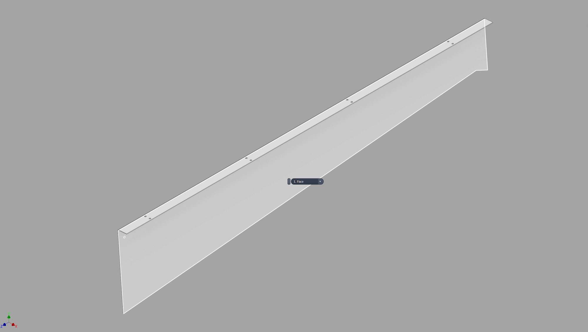
Before — a solid body with the bend approximated by segments.
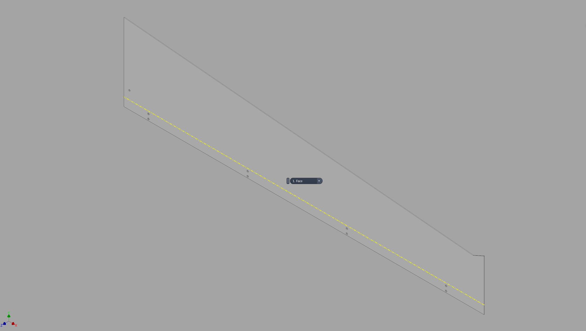
After — the flat pattern, bend line and all.
The proof is in the model tree. Where there was a single unrecognised solid, there is now a Folded Model and a Flat Pattern — the part has become something Inventor's sheet metal engine understands, and something the laser can be given directly. On a real inherited plate the whole conversion takes about a second and a half.
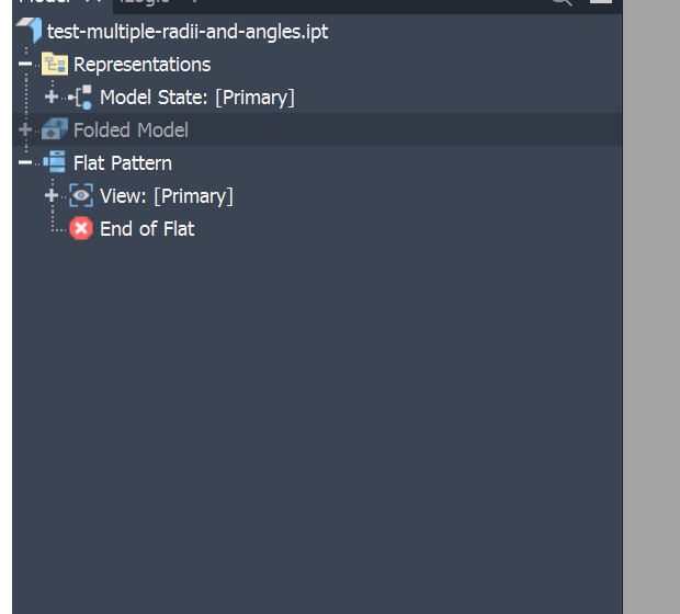
The model tree after one click: Folded Model and Flat Pattern, where before there was neither.
Every step of the conversion runs inside an Inventor transaction, so a failure mid-way through never leaves a half-converted part behind — Inventor rolls the whole operation back. Every step also has its own try/catch with structured logging, so when something does go wrong on an unusual plate, the log points straight at the failing step (workplane creation, cut sketches, radius sketches, cuts, or radii) rather than just reporting a generic "conversion failed".
