
Crowners takes an Inventor assembly and produces the documents a workshop needs to build it. It works in two steps. Analysis reads the assembly, decides what each part is — profile, plate, purchased item — measures sheet thickness, and merges parts that are geometrically identical. Export takes those checked lists and writes the files. The split exists so a misclassified part is corrected before anything is drawn, rather than after. This page is about what comes out of the second step.
A single run writes a package in two layers. The first covers the whole job: one document per kind, for the people who saw, cut and order. The second is a drawing package per subassembly: what travels with the assembly being built. A part appears in both, and that is deliberate. The cutting list for the whole order and the drawing package for one subassembly are read by different people at different moments. Each product can be switched off individually.
The parts list is one workbook with a sheet per table — bar list, plates, purchased, total — plus a printable PDF of each. Columns differ per table because the data does: a cutting length says nothing about a bolt, and a plate thickness says nothing about a profile. A table with no rows is skipped entirely, so an assembly without purchased parts gets no purchased sheet and no purchased PDF.
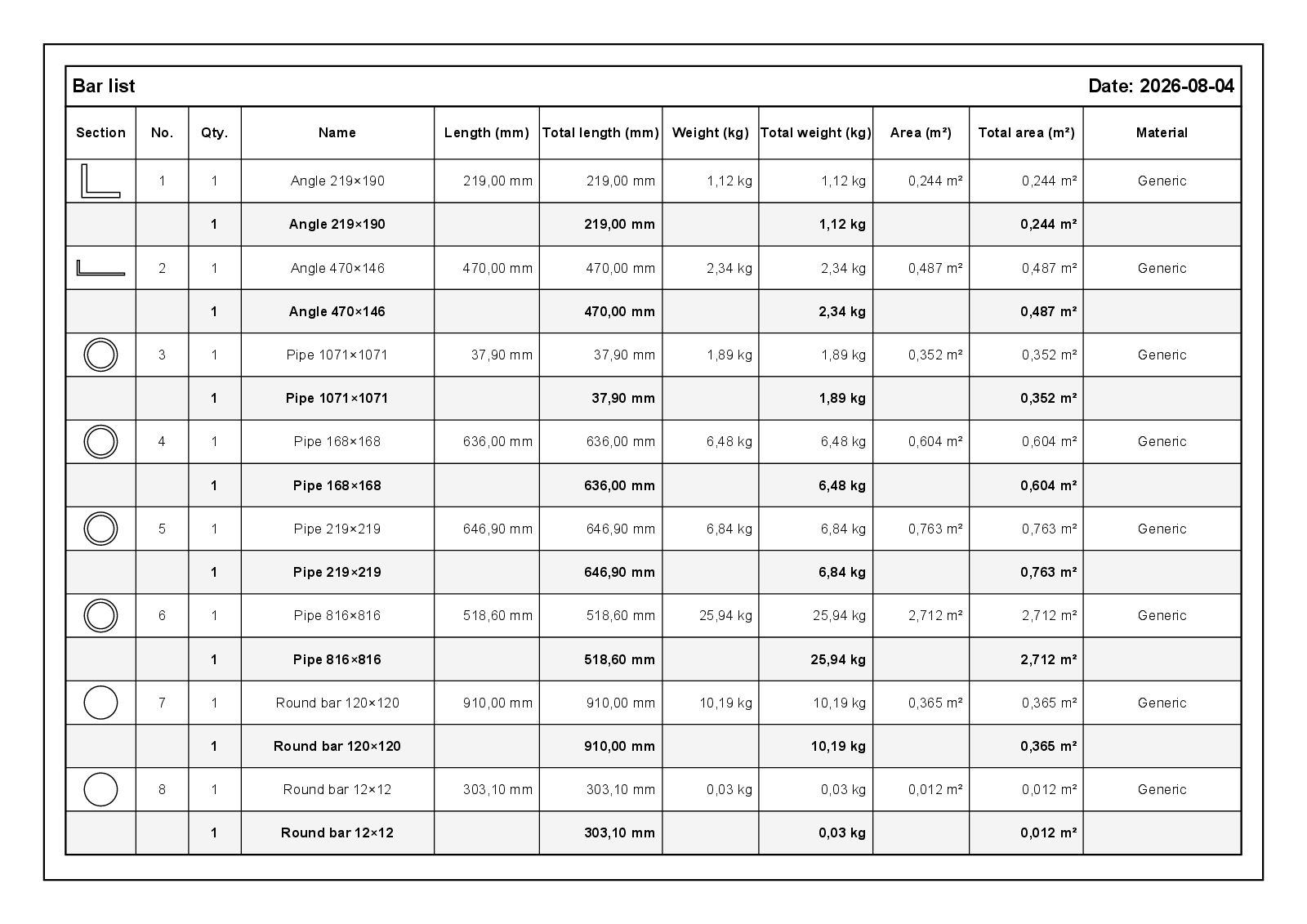
The bar list: cutting length, weight and surface area per section, with the section drawn next to each row.
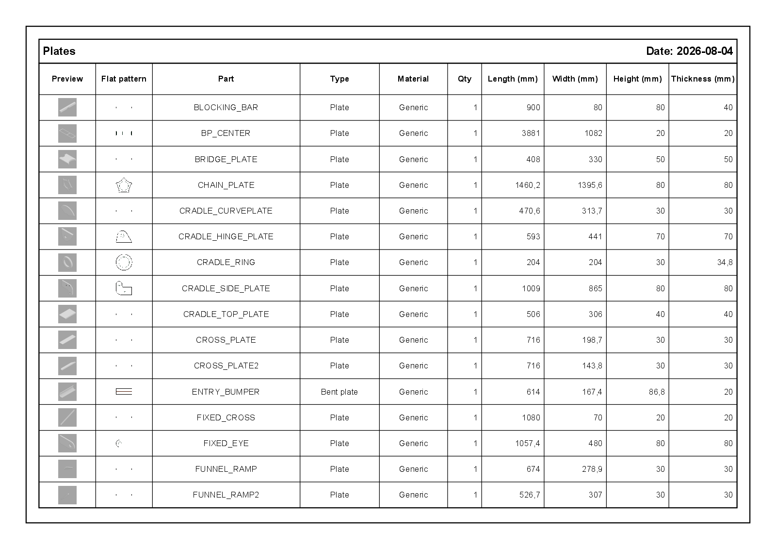
The plates table carries both a 3D preview and the flat pattern, so a bent plate is recognisable before anyone opens a file.
Two combined drawings come with the workbook: every plate of the order on one, every profile on the other, drawn at 1:1. For each part a drawing, a DXF and a STEP file are exported.
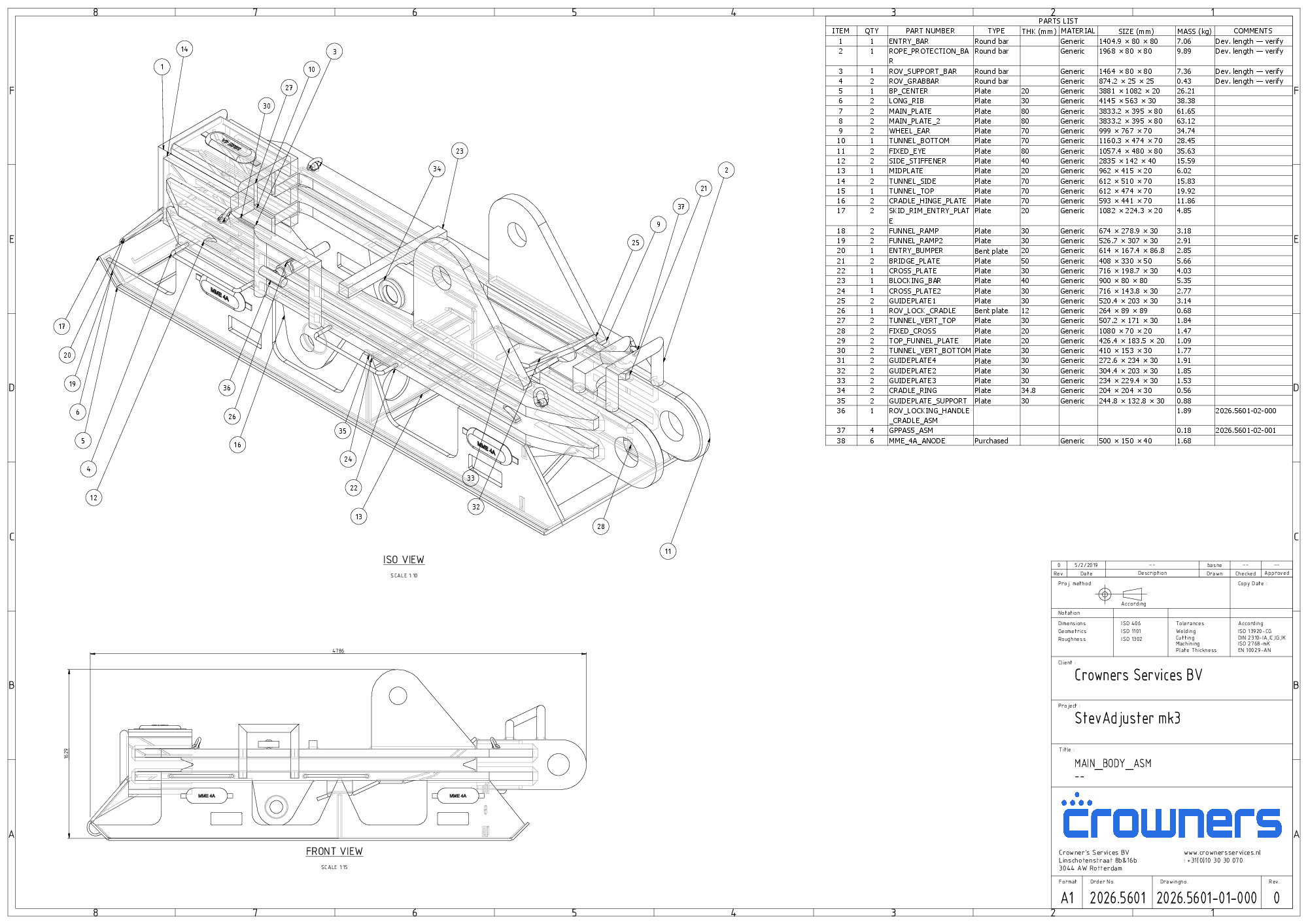
Every ticked subassembly gets one drawing document that is the complete workshop package for it. Sheet 1 is the assembly view with balloons and a first-level parts list. The sheets behind it hold that assembly's own profiles first, then its own plates, each part as a front, top and side view.
Sheet 1: isometric and front view with balloons, a first-level parts list, and a title block filled from a single entry per job.
The parts list is numbered in the order of the sheets behind it: item 1 is the first part on the first part sheet. A balloon leads to a row, and the row's number is where that part is drawn, so nothing has to be searched for. Rows with no sheet — purchased items, subassemblies — follow after.
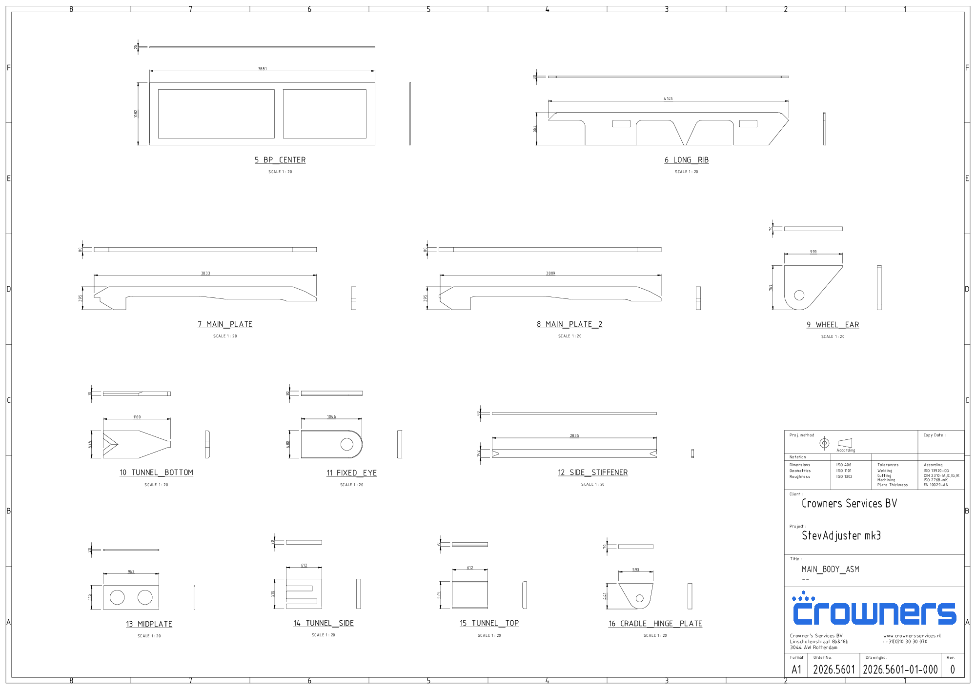
A part sheet: three views per part, position number and name below each, and one scale shared by the whole sheet.
Each sheet uses one scale for everything on it, so parts can be compared against each other without checking how large each one is drawn. A part that no longer fits at that scale starts a new sheet at a scale that suits it. Roughly four parts across sets how big they end up, and that is configurable. There is no flat pattern view: the developed shape ships as a separate DXF, and a fourth view would only repeat it on a sheet that has no room. Dimensions sit on the front view with the thickness on the top view; the side view shows shape and carries no dimension of its own, which would otherwise state the same thickness twice. Sheets are planned before they are drawn rather than packed and rearranged afterwards, so views land where they belong the first time and the finished sheets need no tidying up by hand.
A package documents what hangs directly under its assembly, not what sits inside its subassemblies. So every part is drawn on exactly one package, whatever else is ticked. The connection runs through the parts list: a subassembly's row cites the drawing number of its own package.
Drawing numbers are composed from the order number, the depth in the assembly and a sequence number, so a number says where the assembly sits in the job. The order number is taken exactly as typed and never rewritten. Any number can be overwritten per row and is remembered with the analysis, and ticking an assembly off does not renumber the rest.
<destination>\
   <parts list>.xlsx                    <- one sheet per table
   <parts list>-<table>.pdf             <- a printable PDF per table
   <assembly>-Plates.idw   / .dwg       <- every plate, 1:1
   <assembly>-Profiles.idw / .dwg       <- every profile, 1:1
   STEP\
      <part>.stp ...
   Drawings\                            <- one package per assembly
      <assembly>\
         <assembly>.idw
         <assembly>.pdf                 <- all sheets in one PDF
         <assembly>_<sheet>.dwg         <- one DWG per sheet
         <subassembly>\
            <subassembly>.idw / .pdf / .dwg per sheet
   _work\                               <- the working copy
   Previews\
   <session>.json                       <- the saved analysis
The destination folder after one export. An assembly used in several places gets one package, at the first place it appears.
Re-exporting into a folder that already holds output asks once, before the run starts, with a file count per product: replace everything, fill only the gaps, or cancel. Nothing is deleted — the working copy and the saved analysis live in the same folder and are not output.
Analysis copies the assembly to a working folder and works only on that copy, so the source files are never touched. It splits multi-body parts where asked, classifies each part, measures the real material thickness of every plate and converts solid plates to sheet metal so a flat pattern exists, then merges geometrically identical parts into one row with a summed quantity. Mirrored variants stay separate — they are not interchangeable in the workshop. What analysis concludes is written back onto the working copies as iProperties, which is why the parts lists on the generated drawings fill themselves and purchased rows say "Purchased" rather than nothing.
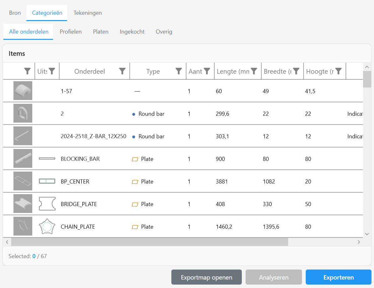
The result tabs after analysis. Everything is reviewable before a single drawing exists.
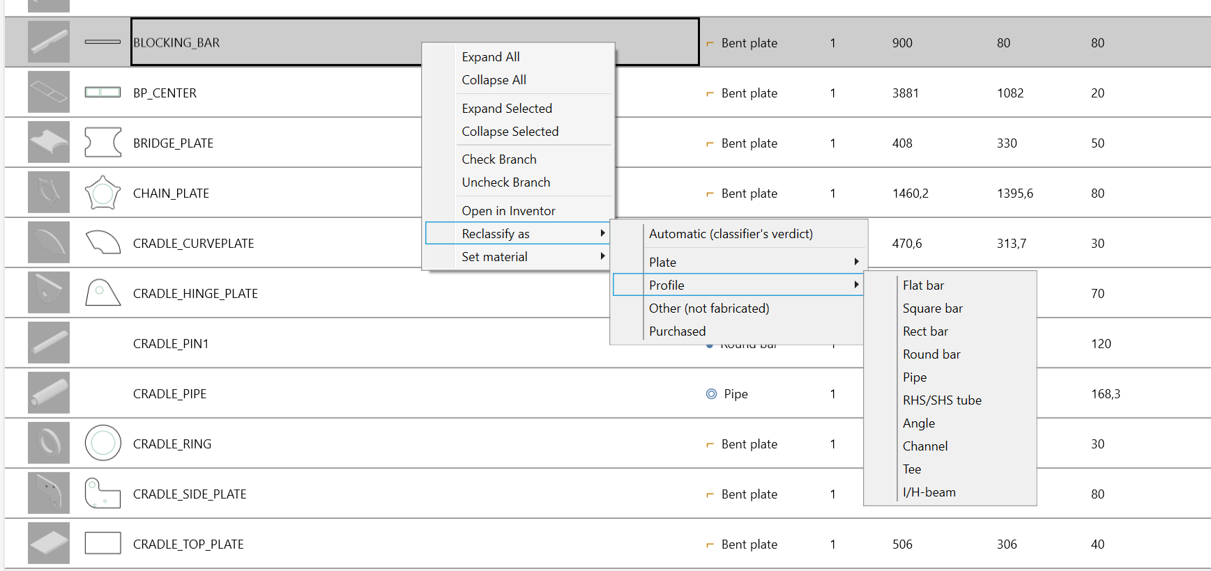
A verdict that is wrong is corrected in place — right-click, reclassify, and the export follows the correction.
The Drawings tab decides which assemblies get a package, and shows the drawing number each one will be filed under. Level checkboxes tick a whole depth at once — the difference between one click and seventy on a large job — and report what is actually selected rather than remembering the click, so a level goes half-filled as soon as one assembly under it is unticked. Assemblies marked purchased, reference or phantom in the model start unticked, since those are not built.
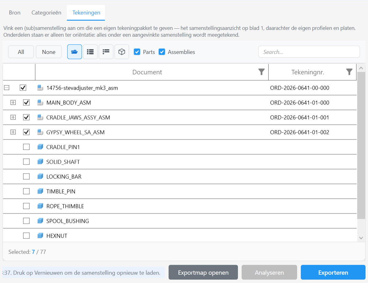
Choosing which assemblies get a package, with the drawing number each will carry.
