
Every container Buijse builds used to mean an engineer cloning a master assembly, plugging in the customer's dimensions, regenerating the model, generating drawings for each sub-assembly, exporting cutting lists, and running STEP and DXF exports for the laser-cut parts — hours of click-through work per order, with plenty of room for human error. The add-in collapses that into entering an order number and clicking Generate.
The whole thing runs from a panel in Inventor itself, so the engineer never leaves the tool they are already working in. There are three ways in. The usual one is the order number: the add-in looks the order up in the company's project system, fills in the customer-facing values, and shows them for checking before any geometry is built. A second tab covers orders that do not come from that system, where the same values are entered by hand. A third points at a project that has already been generated and re-runs its outputs — useful when only a cutting list needs refreshing.
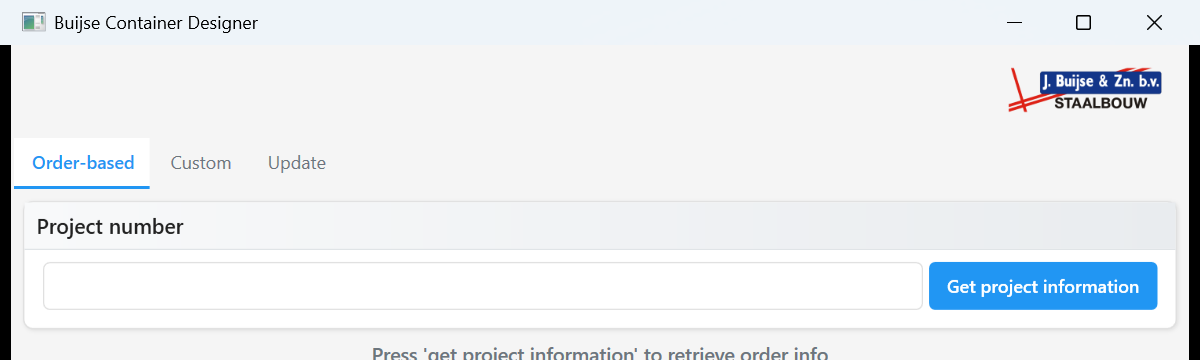
Enter the order number and the rest fills itself in.
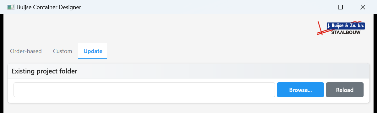
Or point at an existing project and re-run its outputs.
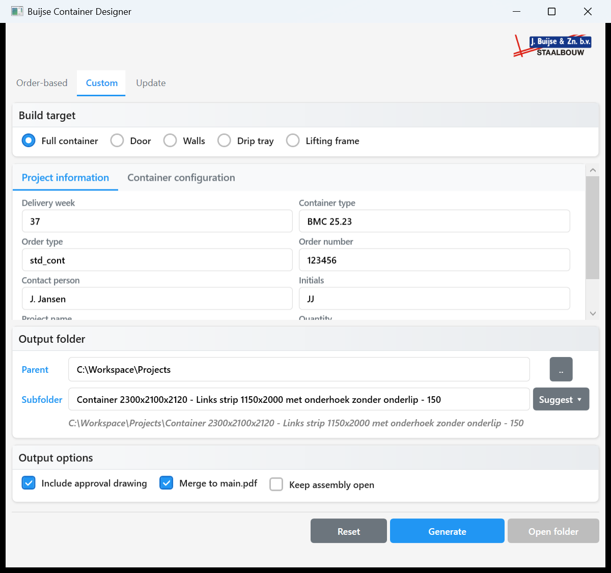
Everything the configurator drives is on one screen: the container envelope, the door opening and where it sits, the door type, the floor type, which part of the container to build, and which outputs to produce. The output folder is picked as a parent directory plus a subfolder name — with a suggestion generated from either the project name or a description of the configuration — and the full path is shown before anything runs.
Every value here is written through to the model before it rebuilds, so the drawings that come out match what was entered.
A container is not modelled as one big part. It is split into sub-assemblies — the lifting frame, the drip tray or tread-plate floor, the door and its frame, and the wall cladding — and each one is a self-contained unit that knows how to build itself. Each is registered once with the rules that matter: which source files it is built from for a given configuration, which values it needs, and whether it belongs in this container at all. A container ordered without a drip tray simply never produces one, and everything downstream treats it as absent rather than failing.
The sub-assemblies coming together into a container: lifting frame, floor, door and frame, then the wall cladding.
This is the part that makes the rest work. Rather than modelling every container from nothing, the add-in draws on a library of pre-made assemblies and templates — a door frame, a floor, a lifting frame — that have already been built properly once, and which already have their production drawings attached to them. Generating a container is a matter of picking the right ones for the order, copying them into the new project, and combining them with the geometry that genuinely has to be built fresh for these particular dimensions.
It runs in two passes. The first gathers every source file the configuration needs — templates, individual parts, the driving sketches — into a single copy operation, de-duplicated so nothing is copied twice, with every internal reference rewired to point inside the new project folder. The drawings travel with their models in the same pass. The second pass drives the values through: entered dimensions are pushed into the sketches, values that depend on other values are read back once those have updated and pushed onward, fresh assemblies are created where the order needs something new, and the newly built parts are added into the copied templates.
Because the drawings came along with the assemblies, they update against the new geometry instead of being drawn from scratch. Work that was done carefully once — how a weldment is dimensioned, which views a frame needs, where the section cuts go — is reused on every order rather than repeated. It also means adding a new product variant is mostly a modelling job: build the assembly, draw it once, register it, and the pipeline picks it up.
A full container produces dozens of drawing sheets — an approval drawing for the customer to sign off, a weldment sheet for each door and frame, assembly sheets for the floor and lifting frame, a grating sheet exported as both PDF and DWG, and a sheet for every individual cut piece — all merged into a single PDF alongside the cutting lists and purchase orders. STEP and DXF files are exported for every non-standard part so they can go straight to the laser. A sample of that output:
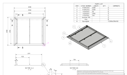
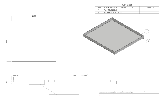
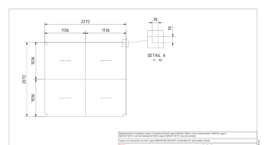
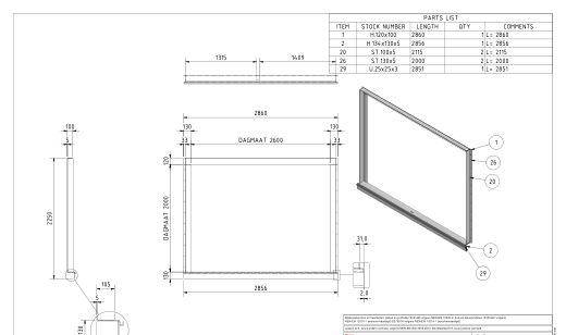
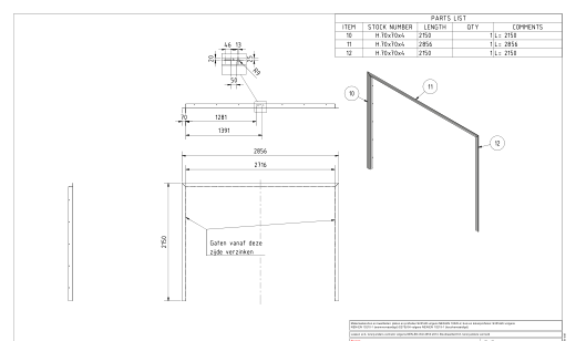
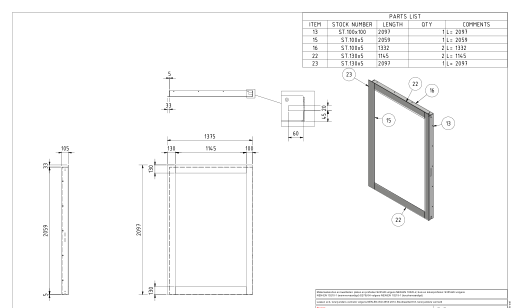
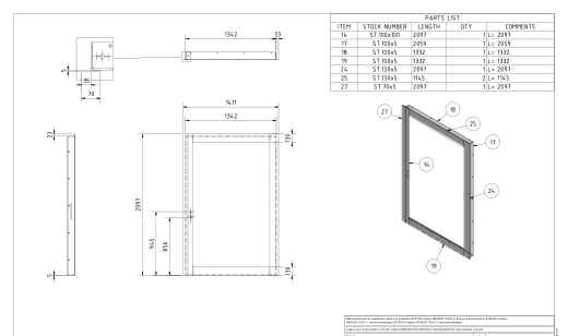
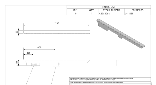
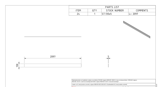
Sheets are shown cropped to the drawing area: these are real production drawings for a client, so the title block is not part of the published images.
Producing a drawing is the easy part; producing one nobody has to correct by hand is not. Where hole patterns overlap other cutouts, the duplicates are found and removed rather than drawn twice. Dimensions that land on top of each other are moved apart before the sheet is exported. The approval drawing the customer signs off is built from scratch — front, top and side views plus a shaded 3D view on one sheet — instead of depending on a template someone has to keep up to date.
Most orders are close to something Buijse has built before. The engineer can start from a catalogued floor or door and change only the fields that differ, with each field either following the catalogue or set by hand. A near-standard order does not have to be typed out in full, and a genuinely custom one is not fighting a template. The door catalogue covers single left, single right, double and a heavier profile, each with its own frame treatment and corner details.
A full container is dozens of steps and takes a while, so a run can be stopped cleanly at any safe point rather than being killed halfway through, and Inventor is left in a sensible state either way. Progress and a running log stay on screen while it works. Alongside the interactive add-in there is a command-line version that takes the same order description from a file and runs without anyone present, which is what would let this hang off a build server or an ERP system later. Under the hood, the lightweight headless version of Inventor handles the file copying and structure analysis, so a full Inventor session is only used where it is actually needed.
